Well Monitoring Control
Sterling Systems & Controls, Inc. has decades of process control and automation expertise. Control and automation systems of various types are custom-engineered and manufactured by Sterling Systems & Controls for a wide range of applications and industries. One example outside of traditional industrial processes is a customer requirement for a municipal Well monitoring control system. This Well monitoring control system consisted of three control panels, one with an Allen-Bradley PanelView Compact touchscreen terminal used to monitor and automatically control the water pumps based on water pressure and flow.
The Sterling System & Controls Well monitoring control system monitors room and building temperature via thermocouples with a 4‐20ma interface. Power loss and generator running inputs are also monitored. Outputs are provided to give permissive signals for ingredient/chemical injections. The operator can use the PanelView interface to configure the system to run one or two pumps in Well #2 and #3 buildings. The three panels are interconnected via a wireless Ethernet network so all field information is relayed to the PanelView terminal. Emergency stops and an alarm beacon/horn are provided on each panel. If any of the E‐Stops are pushed, they will turn off all outputs, but monitoring of input signals will continue.
The main operator interface for this system is a PanelView Compact industrial touchscreen HMI mounted in an enclosure running a process control application custom-engineered by Sterling Systems & Controls. The control panel and PanelView HMI provide all control and equipment status information necessary to run the Well monitoring control process. The system consists of three (3) control panels, one in the main building and one each at the two Well buildings. The remote panels at the Well buildings are connected to the main building panel via a radio connection. Antennas and antenna cables are provided by Sterling Systems & Controls, Inc.

The Well control screen displays icons for the pumps used in the Well control system. The status of each pump is indicated on the grayscale screen by shade and outline. If the equipment runs in Automatic mode, the circle will be light gray and the box around it will be black. If the equipment is idle in the Automatic mode, the circle will be medium gray and the box light gray. If turned off, the circle will be dark gray and the box around it will be black. If the equipment is faulted, the circle will flash white to dark gray.
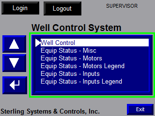
One of four (4) pre-defined security levels controls access to the various functions and features of the control system application. The current security level is displayed at the top right corner of the Main Menu screen.
The system has two built-in logins, with default user names and passwords that can be changed. User names are not case-sensitive, but passwords are. When nobody is logged in, the default security account is active.
Controlling Equipment
Tapping the screen on any pump icon will display a Manual/Off/Auto equipment control screen for the selected equipment. When in Manual mode, the equipment output will be immediately energized/activated/turned on. Pumps running in Manual mode are not interlocked with other pieces of equipment. It will come on and stay on until it is taken out of Manual mode. In the Off mode, the equipment output will be immediately de-energized/deactivated/turned off. Equipment in the Off mode cannot be turned on by the control system, however since this is a software feature, do not perform maintenance on equipment without first following proper lockout/tagout procedures. When in Automatic mode, equipment will be started and stopped automatically as required by the control system. All equipment should be placed in the Automatic mode in normal operating situations. Manual/Off/Auto screens are only available when logged in at maintenance or supervisory security levels.
Equipment Status
The Equipment Status screens can be used to view the current equipment mode and state and the actual I/O points used to determine the equipment status. These screens can be highly useful for troubleshooting and maintenance situations. I/O points displayed on the screens can be traced back to PLC racks and terminal numbers by looking for the I/O point in the drawings provided with the control system. There are also “Set All Equipment to Automatic” and “Set All Equipment to Off” buttons on the Equipment Status – Miscellaneous screen that can be used to control the mode of all equipment.