Dryer Temperature Monitoring
Dryer Temperature Monitoring is an important function in many industrial drying applications. This includes Baking, Food Processing, Pet Food Manufacturing, Animal Feed Milling, and other Industrial and Agricultural applications. The purpose of dryer temperature monitoring is to ensure the quality of the material being processed through the dryer, as well as safety. Sterling Systems & Controls, Inc. has a deep and wide amount of expertise in applications and technologies to custom engineer, manufacture, and supply dryer temperature monitoring controls.
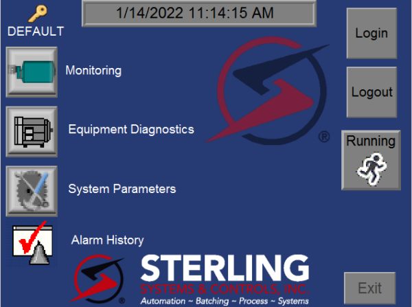
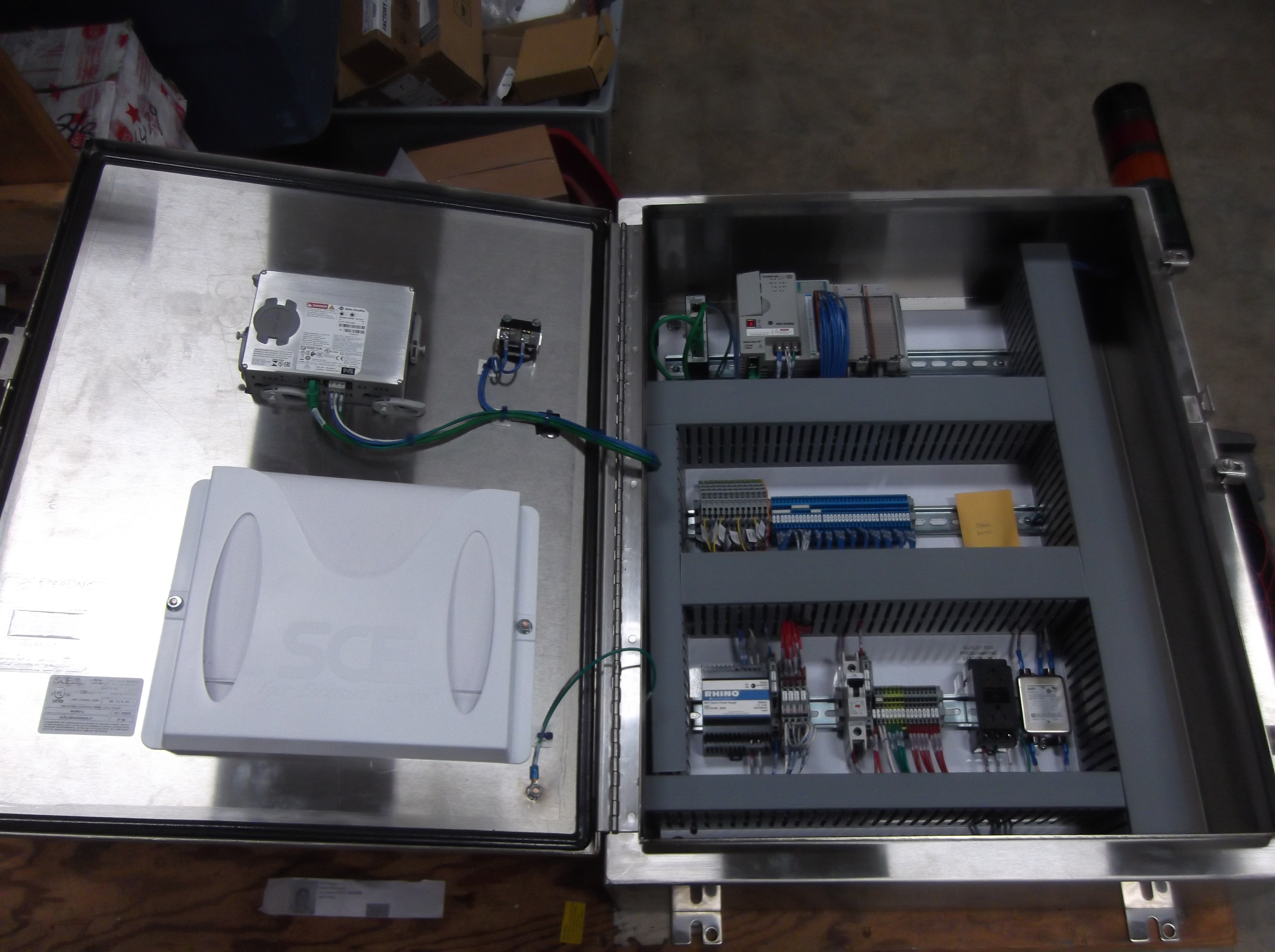
In a specific application within the food processing area, the image shown above is of the home page of an HMI on the control panel of a dryer temperature monitoring system. The monitoring system is incorporated into a single dryer monitoring control panel. The control system includes an Allen-Bradley HMI mounted in the front panel along with the required hardware to support the control logic and monitor the dryer functions, such as the seven (7) temperature sensing modules, power supply, CompactLogix PLC, local alarm indicators, and more.
The seven (7) RTD temperature sensors were also included in the supply by Sterling Systems & Controls, along with the Allen-Bradley PanelView Plus HMI running FactoryTalk View ME. The most important aspect of the system is the Sterling Systems customized software that monitors the temperatures of the dryer and cyclones, which are a part of the overall system. The advantages of the PLC-based dryer temperature monitoring system include the logic to ensure proper progression of alarm and shutdown. The PLC controller also eliminates human error by always being present and monitoring the equipment for abnormal conditions to prevent damage from occurring. The PLC/PV+ panel is pre-wired from the PLC inputs and outputs to terminal strips, with each wire numbered at both ends to help save installation time and maintenance costs. The controls utilize non-proprietary components for ease of replacement from local sources.
The system in this specific application monitors the following equipment from the dryer temperature monitoring panel:
– Dryer Zone #1 Temperature Sensor.
– Dryer Zone #2 Temperature Sensor.
– Dryer Zone #3 Temperature Sensor.
– Dryer Cyclone #1 Temperature Sensor.
– Dryer Cyclone #2 Temperature Sensor.
– Dryer Cyclone #3 Temperature Sensor.
– Post Cyclone Pre-Exhaust Fan Temperature Sensor.
– L1 Alarm Interlock Signal Normally Closed Dry Contact Relay.
– L2 Product Infeed and Burner Interlock Signal Normally Closed Dry Contact Relay.
– L3 Fan and Dryer Bed Interlock Signal Normally Closed Dry Contact Relay.
– L4 High-Temperature Alarm Interlock Signal Normal Closed Dry Contact Relay.
The system HMI has numerous system parameters as well. This includes four levels or conditions with both setpoint and delay for each. In this application, the sequence of system operation is as follows:
- The system will continuously monitor the temperatures from the seven (7) RTD temperature sensors to alert operators of temperature increases, and interlock with the existing system via dry contact relay contacts to allow the decline of elevated temperatures that will be monitored and controlled by others.
- The system responds to temperature increases with four levels of interlocks or notifications:
- Level 1 – Alarm and turn off L1 Alarm Interlock.
- Level 2 – Turn off L2 Product Infeed/Burner Interlock.
- Level 3 – Turn off L3 Fan/Dryer Bed Interlock.
- Level 4 – Activate High-Temperature Alarm.
- For a suppression level to be activated, a temperature sensor must meet or exceed the corresponding temperature setpoint for a minimum programmable time. Once a setpoint suppression level has been activated, the interlock must be reset from the HMI by a logged-in user.
- Alarms and Equipment Interlocking is also accomplished and generally operates as shown below:
- When the system is powered up and monitoring temperatures and no suppression conditions are active, the Green Alarm Light will be active.
- When any setpoint suppression condition is present, the Alarm Horn output is energized and the operator can press the ALARM SILENCE button on the HMI.
- When a Level 1 condition is met, the system will alarm, deactivate the Green Alarm Light and de-energize the L1 Alarm Interlock. The alarm condition will be displayed on the HMI, the Green Alarm Light will remain OFF, and the L1 Alarm Interlock will remain OFF until the condition is reset.
- When a Level 2 condition is met, the system will alarm, activate the Amber Alarm Light, and de-energize the L2 Infeed/Burner Interlock. The alarm condition will be displayed on the HMI, the Amber Alarm Light will remain ON, and the L2 Infeed/Burner Interlock will remain OFF until the condition is reset.
- When a Level 3 condition is met, the system will alarm, activate the Amber Alarm Light, and de-energize the L3 Fan/Dryer Interlock. The alarm condition will be displayed on the HMI, the Amber Alarm Light will remain ON, and the L3 Fan/Dryer Interlock will remain OFF until the condition is reset.
- When a Level 4 condition is met, the system will alarm, activate the Red Alarm Light and de-energize the L4 High Temperature Interlock.
This is just a single example of dryer temperature monitoring. Sterling Systems & Controls custom engineers process controls for a wide range of customer-specific applications and requirements to meet specific objectives.